Saturday, June 12, 2010

Quick Note - Arduino – Serial Programmer

Notes on using the Arduino – Serial Programmer

1. Connect a cable connecting the two 2x4 headers as shown by the red arrow.

2. Make sure that the headers are connected so that pins are connected 1 – 6 with the boards oriented as shown below. The green arrows are pointing at pin 3 on both boards with the pins number top row from left to right numbered 1 – 3 and bottom row 4 – 6.

SerialProgrammerSetup

3. A serial programmer will need to be configured in the Arduino programmers.txt file. Add the commands below to the file. This file in on Windows as of Arduino V018 is located in <arduino$root>\hardware\arduino.

serial.name=Serial
serial.communication=serial 
serial.protocol=dasa

4. The Arduino preferences file can be updated to print more information during the programming process by adding

  upload.verbose=true

On Windows this file is located in and the arduino directory in a users Application Data directory (AppData\Roaming in Windows 7).

5. Burning the boot loader did not work with the Prolific USB Serial Cable under Windows 7. Ended up using hardwired COM port on Windows XP system. Didn’t troubleshoot.

Thursday, June 10, 2010

Home Monitoring System – Electricity Monitoring

My latest activity is a home monitoring system. My starting point is electricity usage. Once I have that up and running I plan to expand into other areas.

After spending some time with Google I found a number of both commercial products and opensource solutions. All of them appear to be based on one of two approaches.

The first approach is to use a current transducer which is installed on the feeder cables for the main electrical panel. The second approach, and the one I have chosen for now, is to setup a sensor to read the electric meter.

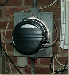
I my case I have an electric meter that has a spinning disk. The disk has a black stripe on it. I have rigged a high intensity LED that shines on the disk and am using a photo resistor that measures the reflection from the LED off the spinning disk. The photo resistor is connected to an analog pin on an Arduino. Every time the black stripe passes in front of the photo resistor the resistance increases and the resulting voltage on the analog pin decreases.

One challenge I faced was that no matter how well I covered the meter while still allowing it to be read I was not able to get it to the point where the changing ambient light during the day and night didn’t affect the baseline. The way I solved the problem was to average the last 500 readings as the baseline. The allows the baseline to move up and down and I determine a rotation has occurred by looking for a delta.

Below is the whole setup with the front cover removed.

image

This is a blow up of the actual sensor. I used a block of wood with two holes drilled in it. One hole has the LED in it and the other the photo resistor.

image

Here is what the setup looks like with the front cover on it. The open slot at the top allows the dials to be read. I am hoping that the electric company will agree with this the next time they come around to read the meter.

image

For now the wires go through the wall and are terminated on a Boarduino from Adafruit which is connected to a laptop via a FTDI USB Board from Sparkfun.

The next step will be to add local storage to the micro processor and a wireless link to allow the data to be read from a monitoring system.

More to come…

Wednesday, June 9, 2010

Bicycle Trainer

Well I haven’t been doing a good job of posting  what I have been up to.  Here is an installment about my work to create an interactive bicycle trainer.  The work was done during the winter of 2009/2010.

Back in March I posted that I had been working to make my winter time bicycle training more interesting.  During the past winter I worked up three different sensors to interface my bicycle to an Arduino.  The data that is captured by the Arduino is sent to my PC via the USB connection and fed into a program written using openFrameworks that runs on the PC and provide graphic feedback.

For anyone who doesn’t know “openFrameworks is an open source C++ toolkit for creative coding.”  It has a number of excellent examples to get you started and also has a number of routines to interface with the Arduino.  I strongly suggest that anyone interested in interfacing the Arduino with a PC that has programming experience take a look at it.

 image

As you can see in the above screen shot the program displays the time I have been riding, the miles per hour, the cadence and the number of miles ridden.  Surrounding this information is a track with a red dot that is updated as I ride.

image

Here is the first sensor I wired up.  This was built using an old Cateye bicycle computer sensor which picks up rotations of the wheel and pedal strokes using sensors mounted on the frame and magnets on the wheel and pedal.

This should have been a simple build but turned out to be a real challenge.  I was riding on a set of rollers on a piece of plywood to protect the carpet.  The sensor would feed data to the Arduino for a while but then the Arduino would start giving crazy readings, locking up and rebooting.

To make a long story short it appears that the band that connects the front roller with the back roller was generating static electricity rubbing on the plywood.  This setup would run for a while as I was holding on to the wall to get started which must have been gounding the whole setup.  I solved the problem by placing an antistatic mat between the rollers and the plywood.

image 

The second setup was built with a set of infrared LEDs.  The transmitter and the receiver are mounted to a plastic U I fabricated and then a black plastic strip mounted to the counter balance breaks the beam which is connected to an interrupt on the Arduino.  This setup doesn’t support cadence.

image

The final rig I built was using a hall effect sensor and magnet from adafruit.  The sensor is connected to the bike frame using velcro and the magnet is connected to a spoke using a bolt that has been cut down the middle.  This setup also doesn’t support cadence.

All three of the sensor setups worked well.  By the time I had complete the initial experiments with sensors and got the openFrameworks program setup it was time that I could start riding outside again.

I plan to pick this project back up again this coming winter when I move my riding back inside.