My latest activity is a home monitoring system. My starting point is electricity usage. Once I have that up and running I plan to expand into other areas.
After spending some time with Google I found a number of both commercial products and opensource solutions. All of them appear to be based on one of two approaches.
The first approach is to use a current transducer which is installed on the feeder cables for the main electrical panel. The second approach, and the one I have chosen for now, is to setup a sensor to read the electric meter.
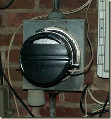
I my case I have an electric meter that has a spinning disk. The disk has a black stripe on it. I have rigged a high intensity LED that shines on the disk and am using a photo resistor that measures the reflection from the LED off the spinning disk. The photo resistor is connected to an analog pin on an Arduino. Every time the black stripe passes in front of the photo resistor the resistance increases and the resulting voltage on the analog pin decreases.
One challenge I faced was that no matter how well I covered the meter while still allowing it to be read I was not able to get it to the point where the changing ambient light during the day and night didn’t affect the baseline. The way I solved the problem was to average the last 500 readings as the baseline. The allows the baseline to move up and down and I determine a rotation has occurred by looking for a delta.
Below is the whole setup with the front cover removed.
This is a blow up of the actual sensor. I used a block of wood with two holes drilled in it. One hole has the LED in it and the other the photo resistor.
Here is what the setup looks like with the front cover on it. The open slot at the top allows the dials to be read. I am hoping that the electric company will agree with this the next time they come around to read the meter.
For now the wires go through the wall and are terminated on a Boarduino from Adafruit which is connected to a laptop via a FTDI USB Board from Sparkfun.
The next step will be to add local storage to the micro processor and a wireless link to allow the data to be read from a monitoring system.
More to come…


No comments:
Post a Comment