Tonight I started working on the wheel encoders for aBot.
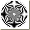
I assembled one of the XWheels and put the 64 segment encoder disk shown below on the back of it. I found the encoder disk on the Robot Gestation website in a very good article on IR Sensors.
I mounted the wheel on one of the servos and clamped the servo in a vice so that the back was pointing up. Above the wheel I positioned one of the QTR-1RC sensors and wired it back to the Boarduino with the signal pin connected to the d2 pin. I connected the servo to four AA batteries and connected the signal pin from the servo to the d5 pin.
The next step was to create a simple sketch which would both drive the servo and charge the reflective sensor and record the amount of time it took for the sensor’s signal pin to go from high to low.
Arduino Sketch
#include <MsTimer2.h>
#include <Servo.h>
#define RRSPIN 3

Servo leftServo;

volatile boolean chargeRS;
volatile unsigned long leftRSStartTime;
volatile unsigned long leftRSTimer;

void chargeRSISR() {
  chargeRS = true;
}

void leftRSISR() {
  leftRSTimer = micros() - leftRSStartTime;
}

void setup() {
  Serial.begin(57600);
  Serial.println("Starting...");
  leftServo.attach(5);
  leftServo.writeMicroseconds(1600);
  attachInterrupt(0, leftRSISR, FALLING);
  chargeRS = false;
  MsTimer2::set(2, chargeRSISR); // 2ms period
  MsTimer2::start();
}

void loop() {
  if (chargeRS) {
    pinMode(LRSPIN, OUTPUT);    // make line an output
    digitalWrite(LRSPIN, HIGH); // drive line high

    delayMicroseconds(10);      // charge line

    pinMode(LRSPIN, INPUT);     // make line an input
    leftRSStartTime = micros();
    digitalWrite(LRSPIN, LOW);  // disable pull-up!
    chargeRS = false;
  }
  if (leftRSTimer) {
    Serial.println(leftRSTimer);
    leftRSTimer = 0;
  }
}
When I ran the sketch I expected to see the amount of time for the capacitor on the reflective sensor to discharge would vary depending on if the sensor was over a black or white stripe on the wheel.
I have to say when I graphed the results I was a bit surprised.
The difference between capacitor discharge times over the black and white stripes showed up. As expected the faster the wheel rotated the narrow the width of the intervals was.
What surprised me as that the series of discharge intervals change forming a second set of peaks and valleys that also decrease in width the faster the servo spins. I am not exactly sure what causes this “macro” interval.
More to follow…


No comments:
Post a Comment